Motor Configurator Tutorial
Automatic Motor Design Demonstration
This demonstrator shows how a fairly complex task of engineering and designing a custom fractional horsepower electrical motor can be completed over the web. It is NOT a complete design application; its purpose is rather to illustrate the automatic over-the-web design capability that can be created using Design Power’s Design++ technology. This demonstrator is derived from an existing real application used in production today. For information on this real application in production, read this Nidec Motor Corporation (NMC) success story on Design Power’s web page.
This demonstration illustrates the use of 3D views, 2D drawings, and various reports for conveying the design results. The 3D motor model can also be viewed as a VRML rendition, which requires a separate VRML viewer plugin. Installing the VRML viewer is optional!
You, in your role as the visiting designer, may have already
registered your personal account, with your email address and optional
password.
With
this Tutorial in hand, you are now ready to embark on engineering and designing
your first fractional horsepower electrical motor.
The Design Task
You are designing a motor for one of two applications, one
is used for driving a condenser fan and the other is for driving a room air
conditioner. The designer first focuses
on selecting the primary performance criteria and then on refining the design
with additional specifications taking into account mounting and environment
variables. The primary results are the
design of the shaft, the rotor, and lamination stacks.
Managing Projects
Before
proceeding to the configuration interface, you will need to create a project to
hold your input data and design results.
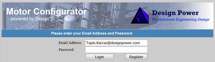
After you log in using your email address and optional password, the
demonstrator then lets you create a new project using your own project
identifier.
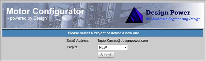
Click “Submit” to
get to the new project dialog.
You may create any number of projects, although we reserve
the right to purge them from time to time.
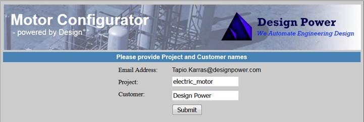
Each project will contain one set of design input along with the 3D
& VRML models, 2D drawings, and various reports that you requested from the
Motor Configurator. Click on “Submit” to create the project. This will open the first of the two main
configuration forms. To create another
project or to switch projects, just click on the “Back to Projects” button on the configuration forms.
The Configuration Process
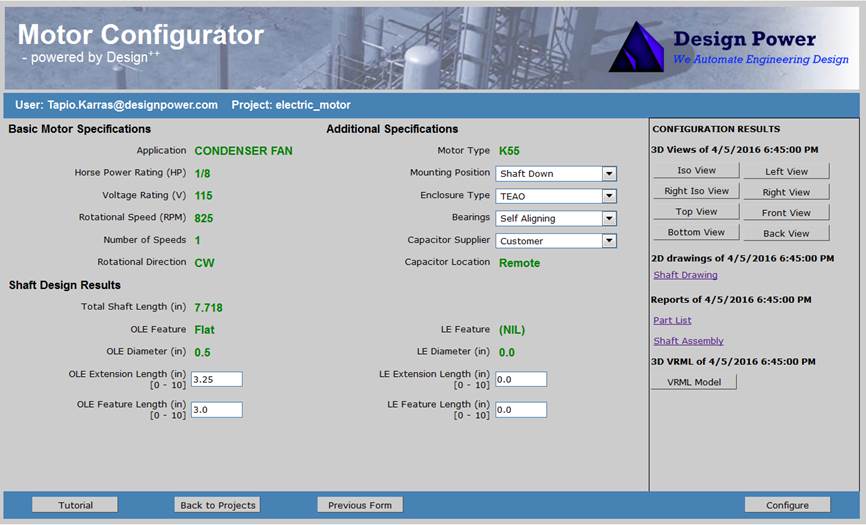
You have successfully reached the Basic Motor Specifications form.
Your email address and project name appear under the banner. The input pane below is populated with a set
of list boxes which contain a set of default selections. At the bottom there are four buttons, the “Tutorial”
button to bring you to this page, a “Back
to Projects” button to access your projects, “Next Form” button (initially greyed out) to access the additional
specifications form, and a “Configure”
button to start the configuration process.
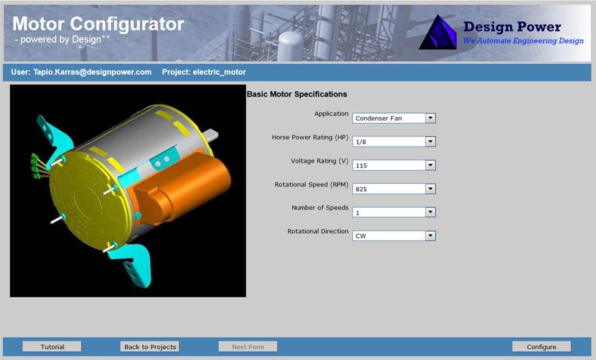
Quick Start
This tutorial examines each of the configuration options in detail, but let's do a quick configuration first using the default values. The input will be the same as in the sample view of the Basic Motor Specifications form above (Application = Condenser Fan, Horse Power Rating (HP) = 1/8, Voltage Rating (V) = 115, Rotational Speed (RPM) = 825, Number of Speeds = 1, and Rotational Direction = CW). Configure your first motor using these default settings by clicking the “Configure” button.
The configuration request is sent to the server, which starts the configuration process. You can follow the motor configuration progress in the Additional Specifications form that opens.
Configuration Results are shown on the right-hand side panel. A list of 3D views, 2D drawings (Shaft Drawing), various reports (Part List Report & Shaft Assembly Report), and a 3D VRML model appear with the date and time of the configuration. You can view the selected views, drawings, and reports by clicking on respective links.
When the configuration is completed, you can specify the
details of this motor and rerun the configuration.
But first, let us look at the motor. If you have a VRML viewer, you can open it by clicking the “VRML Model” button at the bottom of the Configuration Results panel. This will open the viewer with the configured motor model. You may click the “VRML Model” button to view the configured 3D VRML motor model.
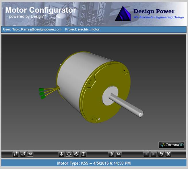
You have now successfully created, documented in 3D and
studied your first automatically engineered and designed fractional electrical
motor.
Additional
Specifications
In the Additional Specifications form notice that the Basic Motor
Specifications displayed in green are fixed. If you wish to change the Basic Motor
Specifications, click the “Previous Form” button, which will bring back
the Basic Motor Specifications form. Now
let’s do some detail design:
1. Change the “Enclosure Type” to “Open Dripproof” and click “Configure”. Once completed you can refresh the VRML viewer by clicking the “VRML Model” in the Configuration Results panel.
2. Notice that the motor now has vent openings both on the end plate and on the cover. The locations of these vent holes are dependent on the “Mounting Position”, that is, if the shaft is mounted “Shaft Up” or “Shaft Down”. Notice also that the motor has three leads.
3. Change the “Capacitor Supplier” from Customer to “Emerson”. Notice that the fixed “Remote” value for “Capacitor Location” changes to a list box with “Remote” and “Shell” as options. Select “Shell” and click “Configure”.
4. The configured motor now has a capacitor cover mounted on top of it. In addition the number of leads is reduced to 2 as the capacitor is connected to the motor internally.
5. Increase the “OLE Extension” to 6.25. The OLE Extension is the operating end extension of the shaft, which is used to connect to the user’s equipment, in this case the condenser fan. Reduce the “OLE Feature Length” to 1.5. The OLE feature is the flat key -feature at the end of the shaft. Click “Configure” and observe the changes.
6. Go back to Basic Motor Specification form and select the “Room Air Conditioner” application and configure. Note that you now have a two ended motor shaft.
7.
Continue playing around with the options.
Conclusion
This Motor Configurator is only a demonstrator that illustrates the capabilities of Design++ connected to a web-interface. This demonstrator is derived from an existing real application used in production today. For information on this real application in production, read this Nidec Motor Corporation (NMC) success story on Design Power’s web page.

Copyright © 2011-2016
Design Power, Inc. All Rights Reserved.