Building Configurator Tutorial
Automatic Building Design Demonstration
This demonstrator shows how a complex building design task can be specified and completed over the web. It is NOT a complete design application; its purpose is rather to illustrate the automatic over-the-web design capability that can be created using Design Power’s Design++ technology. This specific demonstrator shows the design of a metal building roof supported by frames.
You, in your role as the visiting designer, may have already
registered your personal account, with your email address and optional password.
With this tutorial in hand, you are now ready to embark on
creating your first metal building.
The Design Task
You are designing a rectangular building where one end wall may be straight or skewed. The design focuses on the main structural steel framing members, the metal roof panels, and purlins that run between the frames to support the panels. The overall goal of this design process is to minimize the combined weight and cost of the purlins and frames for the given set of dimensions - the roof panel cost is basically constant for the area being covered.
You will set up the problem for the Building Configurator by
entering a few key dimensional parameters (width, length, height, and skew
offset for the end wall, all measured in feet).
In addition, you may adjust some of the default design assumptions (roof
slope, roof load, default roof member type, and member connection type). You
can also control the output of the program by specifying whether to design all
connection parts (takes a little longer), what drawings and reports you need,
and in what format you want them produced.
Managing Projects
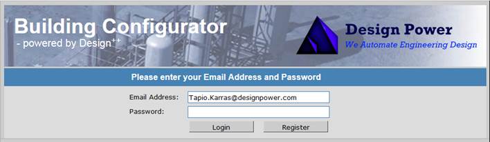
Before proceeding to the configuration interface, you will
need to create a project to hold your input data and design results. After you log in using your email address and
optional password, the demonstrator then lets you create a new project using
your own project identifier.
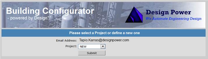
Click “Submit” to
get to the new project dialog.
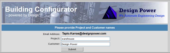
You may create any number of projects, although we reserve
the right to purge them from time to time.
Each project will contain one set of design input along with the 3D
models, 2D drawings, and reports that you requested from the Building
Configurator. To create another project
or to switch projects, just go back in your browser to get to the project
dialog.
The Configuration Process
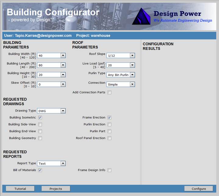
You have successfully reached the main configuration
dialog. Your user and project names
appear on the left under the banner. The
input pane below is populated with a set of combo boxes and check boxes. At the bottom there are three (3) buttons,
the “Tutorial” button to bring you
to this page, a “Projects” button to
access your projects, and a “Configure”
button to start the configuration process.
Quick Start
This tutorial examines each of these options in detail, but let's do a quick configuration first. The input will be the same as in the sample view of the Building Configurator window above (width = 40 feet, length = 80 feet, height = 20 feet, skew offset = 0 feet). Perform these actions.
1. Select “Building Isometric” and “Frame Erection” as your requested drawings. You can request drawings in 3 different formats: DWG (default), DWF, or PDF.
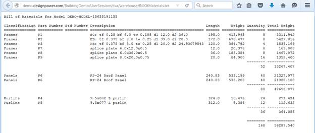
2. Select “Bill of Materials” as the requested report. You can request reports in text format (default) or as Excel files.
3. Click the “Configure” button. Follow the building engineering and design progress in the configuration progress window that opens.
4. When the main configuration dialog reappears, the configuration process is ready.
5. The configuration results are shown on the right-hand side panel. A list of drawings and report appear with the date and time of the design.
6.
View the selected drawings and reports by
clicking on respective links.
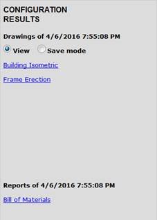
7.
For drawings there are 2 different modes: view
mode (default) and save mode.
In the view mode, the drawings are
shown using an online viewer, 3D Viewer, from http://www.sharecad.org
which allows drawings to be viewed inside the web browser. There is no need to install a separate
browser plugin.
In the save mode, drawings can be
saved locally and viewed with locally installed applications, like AutoCAD for
DWG files.
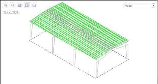
8. The 3D Viewer allows the basic viewing operations. Study the details of the drawings “Building Isometric” and “Frame Erection”.
9.
View the “Bill
of Materials” report by clicking on its link in the reports list. Note the total number of parts.
You have now successfully created, documented, and studied
your first automatically generated metal building design.
The Options
There are two configuration options. The default option is a preliminary design option, which includes all major building parts in the design. By selecting the “Add Connection Parts” option, the building will be designed with all clips and associated bolts.
The outputs of the demonstrator are drawings and reports selected with check boxes under Requested Drawings and Requested Reports. The configuration time is naturally dependent on the number of drawings and reports requested, thus initially while contemplating the concept of the building, only those necessary to help in the conceptual phase should be selected, while the full set may be requested as the final result.
When a new project is opened, the main configuration dialog appears with default configuration options selected and a set of default drawings or reports requested.
When an existing project is opened, the main configuration
dialog settings are set to those used for the last configuration within the
project.
Adding Details
The next step in this tutorial is to add some details to the design. We do that as follows:
1. Select “Add Connection Parts” under Roof Parameters.
2. Click on the “Configure” button again and wait until the engineering and design is complete. This will take a longer time than the initial configuration time as a large number of new parts are added to the building.
3. Bring up the “Building Isometric” drawing.
4. Find an intersection between a purlin line and an inner frame and zoom into that intersection using 3D Viewer’s Zoom tool (or scroll wheel on your mouse). If you have locally installed AutoCAD, you may switch to save mode and open the created drawing in your local AutoCAD. AutoCAD viewing capabilities are of course superior.
5.
View clips and their four fastening bolts to the
attached purlins and frame.
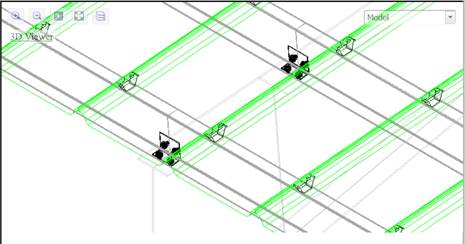
6. Pan along a purlin until you see a roof panel-fastening clip.
7. Zoom out using the “Fit to Window” tool.
8. Find the intersection between a purlin line and an outer frame and zoom in to that intersection.
9. Note that clips now have only a set of two bolts.
10.
Bring up the “Bill of Materials” report.
Note that the total number of parts is considerable higher than the
building without the connection parts.
Making Changes
We have now successfully created the first building with all its details. Let’s make some changes:
1. Deselect “Add Connection Parts”.
2. Change “Building Length” to 100. The length range is 40 to 500.
3. Change the “Skew Offset” to 10.
4. Change the “Connection” selection from Simple to Continuous.
5. Request all drawings and reports.
6. Configure. The considerably bigger building will take a little longer to design and engineer.
7.
Review the resulting drawings and reports for
changes.
Conclusion
This Building Configurator is only a demonstrator that
illustrates the capabilities of Design++ connected to a
web-interface. This demonstrator was
built using simple in-house created rules.
As Design Power’s web page describes, thousands of real metal buildings
are designed each year using applications created by Design Power’s customers
using Design++.

Copyright © 2011-2024
Design Power, Inc. All Rights Reserved.